Application Design & Specifications
I. Introduction
So far, we have defined our application purpose and described its bsuiness requirements.
As a result, the main business entities are starting to emmerge as we delve deeper and deeper into definitions and requirements.
Now it’s time to define our application design.
In this section we will use two UML diagrams, namely, class diagram and use case diagram.
Class diagram is a specific representation of entities, their attributes and their relationships.
On the other hand, Use Case Diagram is a specific representation of a users’s possible interactions with the application. It depicts what a user can do with the application.
Don’t worry if this doesn’t sound familiar to you, you’ll easily get into it as we move forward.
II. ToDo Application Design
If you carefully examine the Application definitions and business requirements, you will find out that those could be depicted by some entities and components.
Here are the main components that you might think of:
- Two main entities, ToDoArea and ToDoTask (we are starting to give our entities significant names)
- Four main use cases for each entity (i.e.
create/delete/search/update) (a user might interact with the application in four different ways for each entity)- (create/delete/search/update) ToDoArea
- (create/delete/search/update) ToDoTask
- Two use cases that involve both ToDoArea and ToDoTask (i.e.
assign/unassign) and which is dealing with update entity relationships: (a user might interact with the application in two different ways when dealing with both of entities)- (assign/unassign) ToDoTask(s) from a given ToDoArea
II.1- ToDoApplication Class Diagram
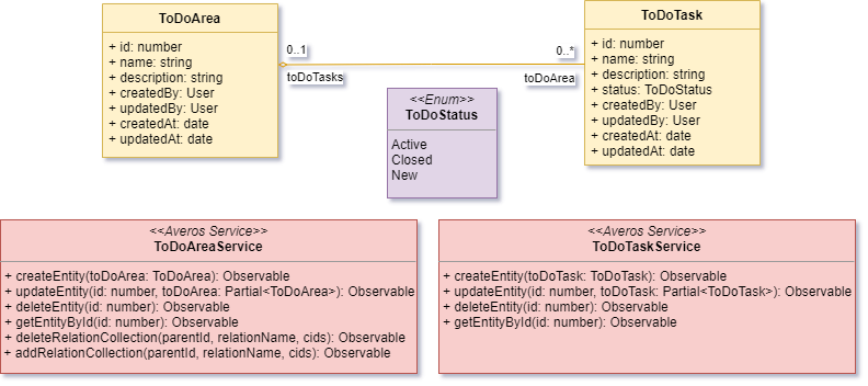
According to our previous study, it is safe to assume that the following class diagram could genuinely describe our main entities and their relationships.
Let’s explain what is happening here.
This class diagram describes ToDoArea entity and ToDoTask as follows:
- an entity named
ToDoAreadefines an Area and has the following seven attributes names or characteristics:id: defines the entity’s identifier. Is of typenumbername: defines the entity’s name. Is of typetextdescription: defines the entity’s description. Is of typetextcreatedBy: defines who created the entity. Is of typeUserupdatedBy: defines who updated the entity. Is of typeUsercreatedAt: defines when the entity was created. Is of typedateupdatedAt: defines when the entity was updated. Is of typedate- a relationship with
ToDoTaskentity: depicted by the fact that zero or one(0..1)ToDoAreacontains zero or many(0..*)ToDoTask
- an entity named
ToDoTaskdefines a Task and has the following seven attributes names or characteristics:id: defines the entity’s identifier. Is of typenumbername: defines the entity’s name. Is of type textdescription: defines the entity’s description. Is of typetextcreatedBy: defines who created the entity. Is of typeUserupdatedBy: defines who updated the entity. Is of typeUsercreatedAt: defines when the entity was created. Is of typedateupdatedAt: defines when the entity was updated. Is of typedatestatus: defines the status of the task. It could be one of these fixed values:Active,ClosedorNew(A task can be new, active or closed. We could have thought about other statuses; but we wanted to keep it as much simple as possible for this tutorial). Since this attribute has a set of predefined values it is of typeenumeration
- Two services for each entity,
ToDoAreaServiceandToDoTaskService.These are the services that manage each entity.
Please keep in mind that you don’t have to know the methods implemented by these services. All what you should know is that:- there are one managing service for each entity as follows:
ToDoAreaServicemanaging the entityToDoAreaToDoTaskServicemanaging the entityToDoTask- these services are responsible for communicating with the backend service (
backend service mockin our case)
II.2- ToDoApplication Use Cases Diagram
According to our previous study we have identified a couple of use cases that define how a given user can interact with our ToDoApplication.
Those use cases might be described by the following Use case diagram.
Again, few things are happening here.
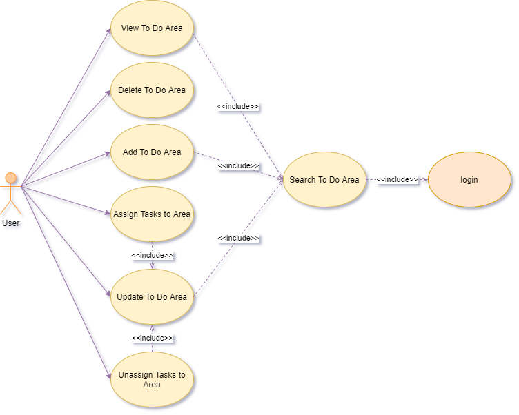
The first use case diagram describes how a user interacts with ToDoArea entity using our application:
- a user can
View/delete/add/updateaToDoAreainstance- a user can
Assign/UnassignaToDoTaskto aToDoArea- a user can
SearchforToDoAreainstances- All these actions are performed while the user is signed into the application (user is in the private context).
- some actions includes a search for
ToDoArea(View,addandupdateaToDoAreaare possible after executing a search action)
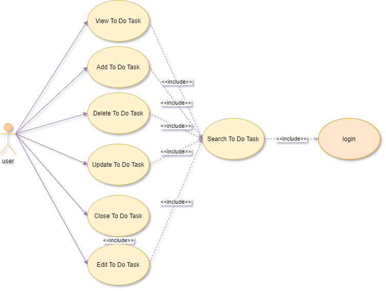
The second use case diagram describes how a user interacts with ToDoTask entity using our application:
- a user can
View/delete/add/updateaToDoTaskinstance- a user can
CloseaToDoTaskinstance- a user can
SearchforToDoTaskinstances- All these actions are performed while the user is signed into the application (user is in the private context).
- All these actions includes a search for
ToDoTask(View,addandupdateaToDoTaskare possible after executing a search action)
ℹ️ Believe it or not, you have done half the work of building your application. Congratulations !
Remember that a clear design specifications is key for a good application.
Now our application design is finished, it is high time we start implementing our application using Averos Designer.
Usually, developing such an application from scratch is considered as a long heavy process which involve environment preparation and hours of coding.
Using Averos Designer you will be able to build this application in minutes.
Next, we will delve deeper into Averos Designer and generate our application.
Let’s do this ! 🚀